-
Carrier Rfl-0601el Manual카테고리 없음 2020. 3. 6. 22:08
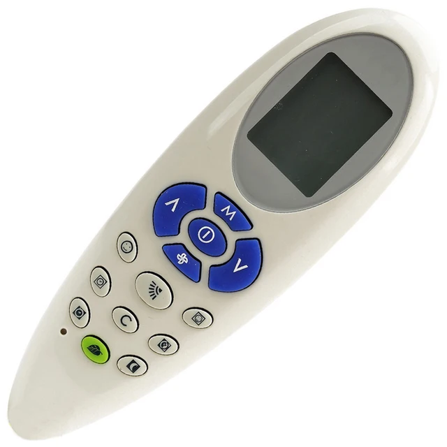
About product and suppliers: Alibaba.com provides 120 carrier surroundings conditioner remote control products. Around 16% of these are usually remote handle, 15% are usually surroundings conditioners, and 10% are usually other consumer consumer electronics.
A broad variety of carrier atmosphere conditioner remote control choices are available to you, such as free examples. There are 120 carrier atmosphere conditioner remote control providers, mainly situated in Asian countries.

The best supplying nation is China (Mainland), which provide 100% of carrier surroundings conditioner remote control handle respectively. Provider surroundings conditioner remote control control items are almost all well-known in Mid East, North America, and Domestic Markét.
Carrier Rfl 0601ehl Manual
You can make sure product protection by choosing from authorized suppliers, including 20 with ISO9001, 13 with Additional, and 1 with ISO/TS16949 certification.
. Control Module Communication.4 Company Comfort System User interface.4 OPERATING Information. Items (cont). Guide/LAG DETERMINATION. CAPACITY SEQUENCE DETERMINATION. Capability CONTROL OVERRIDES Head Pressure Control.27.
Details is transmitted between modules via a 3-cable com- Device 30GTN,Ur munication shuttle bus or LEN (Neighborhood Equipment System). The - - CCN (Carrier Comfort System) bus is also supported. Scam- - nections to bóth LEN ánd CCN busses are produced at TB3. Orange Directed - The MBB has one yellow hue LED. The Carrier Comfort System (CCN) Led pre lit will blink during occasions of network communication. Provider Comfort System (CCN) User interface - The 30GTN,L chiller units can end up being connected to the CCN if desired.
CR-A1 CR-A1 CR-A1 Tale FOR FIG. 1-4 - Compressor Contactor - Signal Breaker - Company Comfort System - Compressor Ground Fault - Cooler Heating unit Thermostat - Circuit - Cool Heater Relay - Compressor Protection and Handle System - Chilled Drinking water Flow Change -. Information COMMUNICATION Interface Fig.
2 - 24 Sixth is v Handle Schematic, Unit Sizes 040-070. Information COMMUNICATION PORT Fig.
Carrier Air Conditioner Manuals Downloads
3 - 24 V Control Schematic, Device Sizes 080-110, 230B-315B Fig. 3 - 24 Sixth is v Control Schematic, Unit Sizes 080-110, 230B-315B.
DATA COMMUNICATION PORT Fig. 4 - 24 V Control Schematic, Unit Dimensions 130-210, 230A-315A, 330A/C-420A/B. LEN (Neighborhood EQUIPMENT System) CEPL130346-01 STATUS Fig.
6 - Enable/Off/Remote Contact Switch, Crisis On/Off Change, YELLOW LED - CCN (CARRIER COMFORT NETWORK) Fig. 5 - Main Base Plank RESET Switch (SIZES 130-210 AND ASSOCIATED MODULES ONLY) and Reset to zero Button Areas. OPERATING Information Sensors - The digital control utilizes 4 to 10 thermistors to feeling temperatures for managing chiller operation.
These detectors are discussed below. 7-10 for thermistor places. Thermistors T1-T9 are 5 eΩ at 77 N (25 G). 040-070 080-110 AND ASSOCIATED MODULAR UNITS. 130-210 AND ASSOCIATED MODULAR Products.When thermistor is certainly viewed from perspective where the compressor can be on the still left and the chiller is on the best. 8 - Thermistor T3 and Capital t4 Locations.
Fable EXV - Digital Expansion Device Fig. 9 - Compressor Thermistor Areas (Capital t7 and T8) Fig. 10 - Typical Thermistor Location (30GTN,R and 30GUN,R 210, 315A, 390A, 420A/W Shown). The area heat range sensor contains a port engine block (SEN) and a RJ11 women con- nector.
The RJ11 connector is utilized to tap into the Carrier Com- fort System (CCN) at thé sensor. To connect the space heat sensor (Fig. Thermostatic Development Valves (TXV) - 30GTN,R and 30GUN,R 040-110 systems are obtainable from the manufacturing plant with standard TXVs with liquid series solenoids. The liquefied line solenoid valves are usually not meant to become a mechanical shut-off.
When provider is needed, use the liquefied line program control device to send down the system. Electronic Enlargement Device Fig. 15) - Regular units are usually outfitted with a bottom close off EXV. This device eliminates the make use of of the liquid line solenoid pumpdown at unit shutdown. An O-ring offers been added to bot- ben of hole assembly to finish a seal off in the valve on shut- lower.
CEBD4-01C Standing RED Directed - Position The capability control algorithm works every 30 mere seconds. The criteria attempts to preserve the departing chilled water tem- perature at the handle point. Each period it runs, the control scans the getting into and causing fluid temperature ranges. The handle deter- mines the rate at which situations are altering and calculates 2 variables centered on these conditions. Table 5A - Part Load Data Percent Displacement, Standard Units Device CONTROL 30GTN,Ur Actions 30GEl,L 040 (60 Hz) 040 (50 Hz) 045 (60 Hz) 045 (50 Hz) 050 (60 Hz) 050 (50 Hz) 060 (60 Hz) 060 (50 Hz) 070 (60 Hz) 070 (50 Hz) 080, 230B (60 Hz) 080, 230B (50 Hz). Desk 5A - Component Load Information Pct Displacement, Regular Systems (cont) UNIT Handle 30GTN,Ur Ways 30GUN,R 100, 255B 270B (50 Hz) 110, 290B, 315B (60 Hz) 110, 290B, 315B (50 Hz) 130 (60 Hz) 130 (50 Hz) 150, 230A, 245A, 255A (60 Hz).Unloaded compressor.